TM-9-2815-205-24 - Page 612 of 856
DISASSEMBLY - Continued
3.
Governor housing assembly removal procedures:
a.
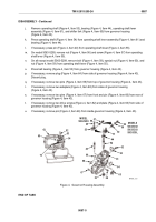
Loosen nut (Figure 3, Item 38) and remove buffer screw (Figure 3, Item 39) and spring
(Figure 3, Item 37) from side of governor housing (Figure 3, Item 43).
b.
Remove retaining clip (Figure 3, Item 32), two flat washers (Figure 3, Item 47), and roller bearing
(Figure 3, Item 48) and control link lever (Figure 3, Item 49) assembly from grooved pin
(Figure 3, Item 46).
c.
If two roller bearings (Figure 3, Item 49) require replacement, support control link lever
(Figure 3, Item 50) assembly on a sleeve (Figure 3, Item 48) in press. Press two bearings out of lever
assembly using bearing and bushing remover (Figure 3, Item 51).
d.
Remove retaining clip (Figure 3, Item 34) and flat washer (Figure 3, Item 35) from pin
(Figure 3, Item 40). Remove differential lever (Figure 3, Item 36) assembly.
e.
If necessary, press pin (Figure 3, Item 33) from differential lever (Figure 3, Item 36).
f.
Remove expansion plug (Figure 3, Item 45) from bottom of governor housing (Figure 3, Item 43).
Discard expansion plug.
g.
Remove special screw (Figure 3, Item 41) and flat washer (Figure 3, Item 42) fastening governor
bearing (Figure 3, Item 44) in governor housing (Figure 3, Item 43).
48
45
44
43
40
51
50
49
46
42
41
32
33
34
35
47
39
38
37
36
49
50
47
MAINT_312
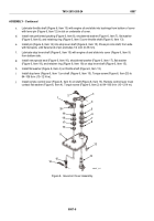
Figure 3.
Governor Housing Disassembly.
h.
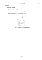
Place governor housing (Figure 4, Item 43), top down, on wooden blocks in press. Using a short
3/8 inch (9.5 mm) diameter rod (Figure 4, Item 52), press operating shaft (Figure 4, Item 53) free of
bearing (Figure 4, Item 54).
i.
Insert 9/16 inch open end wrench (Figure 4, Item 70) between shifter fork (Figure 4, Item 65) and
governor housing (Figure 4, Item 43). Using a 3/8 inch (9.5 mm) diameter rod (Figure 4, Item 52),
press operating shaft (Figure 4, Item 53) out of shifter fork.
TM 9-2815-205-24
0087
0087-4
Back to Top


