TM-9-2815-205-24 - Page 616 of 856
ASSEMBLY - Continued
c.
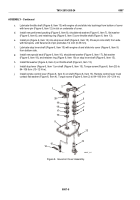
Lubricate throttle shaft (Figure 6, Item 13) with engine oil and slide into bushings from bottom of cover
with lever pin (Figure 6, Item 12) in slot on underside of cover.
d.
Install new preformed packing (Figure 6, Item 8), shouldered washer (Figure 6, Item 7), flat washer
(Figure 6, Item 6), and retaining ring (Figure 6, Item 5) over throttle shaft (Figure 6, Item 13).
e.
Install pin (Figure 6, Item 14) into stop lever shaft (Figure 6, Item 15). Press pin into shaft, from side
with flat spots, until flared end of pin protrudes 1/4 inch (6.35 mm).
f.
Lubricate stop lever shaft (Figure 6, Item 15) with engine oil and slide into cover (Figure 6, Item 9)
from bottom side.
g.
Install new special seal (Figure 6, Item 16), shouldered washer (Figure 6, Item 17), flat washer
(Figure 6, Item 18), and retainer ring (Figure 6, Item 19) on stop lever shaft (Figure 6, Item 15).
h.
Install flat washer (Figure 6, Item 4) on throttle shaft (Figure 6, Item 13).
i.
Install stop lever (Figure 6, Item 1) on shaft (Figure 6, Item 15). Torque screw (Figure 6, Item 20) to
84–106 lb-in (10–12 N·m).
j.
Install remote control lever (Figure 6, Item 3) on shaft (Figure 6, Item 13). Remote control lever must
contact flat washer (Figure 6, Item 4). Torque screw (Figure 6, Item 2) to 84–106 lb-in (10–12 N·m).
2
3
4
5
6
7
8
1
12
13
14
15
16
17
18
19
20
9
MAINT_315
Figure 6.
Governor Cover Assembly.
TM 9-2815-205-24
0087
0087-8
Back to Top


