TM-9-2815-205-24 - Page 620 of 856
ASSEMBLY - Continued
m.
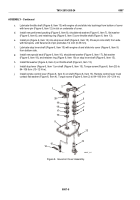
Support governor housing (Figure 9, Item 43) in press with upper end of shaft (Figure 9, Item 54)
against bed of press. Align flat on shaft with flat in bore of shifter fork (Figure 9, Item 65). Place sleeve
over shaft and against fork. Press fork tight against shoulder on shaft.
n.
Place bearing (Figure 9, Item 53), shield side toward the shifter fork (Figure 9, Item 65), on lower end
of shaft (Figure 9, Item 54). With upper end of shaft supported, press bearing against shoulder in bore
of governor housing (Figure 9, Item 43) using sleeve against inner race of bearing.
o.
Lubricate bearing (Figure 9, Item 44) and bearing (Figure 9, Item 53) with engine oil.
p.
Support control link lever (Figure 9, Item 50) on sleeve (Figure 9, Item 48). Place roller bearing
(Figure 9, Item 49), numbered side up, on lever and press flush using governor cover bearing installer
(Figure 9, Item 71). Invert lever and install second roller bearing in same manner.
48
44
43
54
71
50
49
53
65
MAINT_318
Figure 9.
Governor Housing Bearing Installation.
TM 9-2815-205-24
0087
0087-12
Back to Top


