TM-9-2815-205-24 - Page 618 of 856
ASSEMBLY - Continued
3.
Governor housing assembly procedures:
a.
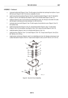
If removed, press two pins (Figure 8, Item 69) into top of governor housing (Figure 8, Item 43) until
pins bottom out.
b.
If removed, apply sealing compound to two adapters (Figure 8, Item 68) and tap into place until they
extend 1-7/16 inches (36.51 mm) beyond governor housing (Figure 8, Item 43).
c.
If removed, press pin (Figure 8, Item 66) into rear of governor housing (Figure 8, Item 43) until it
extends 3/8 inch (9.5 mm) beyond housing.
d.
If removed, press two pins (Figure 8, Item 67) into front of governor housing (Figure 8, Item 43) until
they extend 7/16 inch (36.51 mm) beyond housing.
e.
If removed, install plate (Figure 8, Item 63) and two drive screws (Figure 8, Item 62) on governor
housing (Figure 8, Item 43).
f.
If removed, press pin (Figure 8, Item 46) into governor housing (Figure 8, Item 43). Pin must extend
1.055–1.060 inches (26.80–26.92 mm) above housing for model 5063-5299 and 1.497–1.504 inches
(38.02–38.20 mm) above housing on all except model 5063-5299. Measure pin using depth gage.
g.
Support lower end of operating shaft (Figure 8, Item 54) in press. Start bearing (Figure 8, Item 44) on
shaft, numbered side up, and press bearing against shoulder on shaft using a sleeve positioned
against inner race of bearing.
h.
If removed, press pin (Figure 8, Item 40) in operating lever (Figure 8, Item 55) until it bottoms out
on shoulder.
i.
On model 5063-5299, install nut (Figure 8, Item 56) and screw (Figure 8, Item 57) in operating shaft
lever (Figure 8, Item 55).
j.
On all except model 5063-5299, install bolt (Figure 8, Item 58), special nut (Figure 8, Item 60), and nut
(Figure 8, Item 59) in operating shaft lever (Figure 8, Item 55).
k.
Start operating shaft lever assembly (Figure 8, Item 61) on operating shaft (Figure 8, Item 54) with flat
on shaft in flat in lever bore and pin (Figure 8, Item 40) up. Using a sleeve, press lever tight against
inner race of bearing (Figure 8, Item 44).
l.
Insert lever, bearing, and shaft assembly (Figure 8, Item 72) through bore inside governor housing
(Figure 8, Item 43). Place shifter fork (Figure 8, Item 65) on lower end of shaft with finished cam
surfaces facing rear of governor housing.
TM 9-2815-205-24
0087
0087-10
Back to Top


