TM-9-2815-205-24 - Page 610 of 856
DISASSEMBLY
NOTE
Before disassembly of governor, clean entire unit and inspect for worn or damaged parts.
Repair damaged parts without disassembly of governor wherever possible.
1.
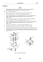
Governor cover removal procedures:
a.
Loosen screw (Figure 1, Item 2) and remove remote control lever (Figure 1, Item 3).
b.
Remove flat washer (Figure 1, Item 4) from throttle shaft (Figure 1, Item 13).
c.
Remove retaining ring (Figure 1, Item 5), flat washer (Figure 1, Item 6), and shouldered washer
(Figure 1, Item 7) and withdraw throttle shaft (Figure 1, Item 13) from bottom of cover
(Figure 1, Item 9).
d.
Remove preformed packing (Figure 1, Item 8) from cover (Figure 1, Item 9). Discard packing.
e.
Loosen screw (Figure 1, Item 20) and remove stop lever (Figure 1, Item 1).
f.
Remove retaining ring (Figure 1, Item 19), flat washer (Figure 1, Item 18), and shouldered washer
(Figure 1, Item 17). Withdraw stop lever shaft (Figure 1, Item 15) from bottom of cover
(Figure 1, Item 9).
g.
If necessary, remove pin (Figure 1, Item 14) from stop lever shaft (Figure 1, Item 15).
h.
Remove special seal (Figure 1, Item 16) from cover (Figure 1, Item 9). Discard seal.
i.
If necessary, remove two tapered pins (Figure 1, Item 12) from bottom of cover (Figure 1, Item 9).
j.
If two bushings (Figure 1, Item 11) require replacement, support governor cover (Figure 1, Item 9) on
two wooden blocks in press and press two bushings from cover using bearing and bushing remover
(Figure 1, Item 10).
2
3
4
5
6
7
8
1
9
10
11
12
13
14
15
16
17
18
19
20
9
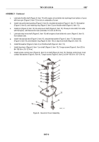
Figure 1.
Governor Cover Removal.
TM 9-2815-205-24
0087
0087-2
Back to Top


