TM-9-2815-205-24 - Page 606 of 856
ASSEMBLY - Continued
18.
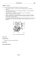
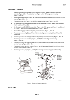
Install turbine housing (Figure 9, Item 3) on center housing (Figure 9, Item 2) and align match marks.
19.
Install turbine V-band coupling (Figure 9, Item 8) and locknut (Figure 9, Item 9). Use following procedure to
tighten clamp:
a.
Install V-band coupling (Figure 9, Item 8) on turbine housing (Figure 9, Item 3) and center housing
(Figure 9, Item 2) so that T-bolt end does not interfere with turbine housing.
b.
Lubricate threads on T-bolt with anti-seize compound.
CAUTION
Do not tighten V-band coupling (Figure 9, Item 8) if turbine housing is misaligned.
Forcing turbine housing into alignment by tightening coupling can damage
components.
c.
Torque locknut (Figure 9, Item 9) to 152–168 lb-in. (17–19 N·m).
d.
Slowly loosen locknut (Figure 9, Item 9) on V-band coupling (Figure 9, Item 8) to approximately
50 lb-in. (6 N·m), then re-torque locknut to 152–168 lb-in. (17–19 N·m).
20.
Align match marks on compressor housing (Figure 9, Item 1) and center housing (Figure 9, Item 2). Install
compressor housing and V-band coupling (Figure 9, Item 6) on center housing. Lubricate threads on T-bolt
with engine oil and torque locknut to 110–130 lb-in. (12–15 N·m).
21.
Install connector (Figure 9, Item 7) to top of center housing (Figure 9, Item 2).
22.
On models 5063-5393 and 5063-539L, install new gasket (Figure 9, Item 10), drain tube (Figure 9, Item 11),
two new lockwashers (Figure 9, Item 12), and two screws (Figure 9, Item 13) to bottom of center housing
(Figure 9, Item 2). Torque screws to 30–35 lb-ft (41–47 N·m).
23.
If removed for models 5063-5392, 5063-5393, and 5063-539L, install inlet screen (Figure 9, Item 4) and seal
(Figure 9, Item 5) on compressor housing (Figure 9, Item 1).
TM 9-2815-205-24
0086
0086-10
Back to Top

