TM-9-2815-205-24 - Page 598 of 856
DISASSEMBLY - Continued
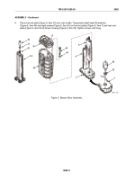
CAUTION
Exercise care when removing compressor housing and turbine housing to prevent damage
to compressor and turbine wheels.
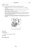
2.
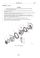
Remove V-band coupling (Figure 2, Item 6) and compressor housing (Figure 2, Item 1) from center
housing (Figure 2, Item 2).
3.
If necessary for models 5063-5392, 5063-5393, and 5063-539L, remove inlet screen (Figure 2, Item 4) and
seal (Figure 2, Item 5) from compressor housing (Figure 2, Item 1).
4.
On models 5063-5393 and 5063-539L, remove two screws (Figure 2, Item 13), two lockwashers
(Figure 2, Item 12), drain tube (Figure 2, Item 11), and gasket (Figure 2, Item 10) from center housing
(Figure 2, Item 2). Discard lockwashers and gasket.
5.
Remove connector (Figure 2, Item 7) from top of center housing (Figure 2, Item 2).
6.
Remove locknut (Figure 2, Item 9), V-band coupling (Figure 2, Item 8), and turbine housing
(Figure 2, Item 3) from center housing (Figure 2, Item 2).
1
4
5
6
2
7
8
3
9
10
11
12
13
MAINT_308
Figure 2.
Turbo Disassembly.
TM 9-2815-205-24
0086
0086-2
Back to Top


