TM-9-2815-205-24 - Page 594 of 856
ASSEMBLY - Continued
NOTE
Add or remove shims between gear and rotor spacer until blower clearances
meet specifications.
18.
Using stacked thickness gages, obtain blower clearances as follows:
a.
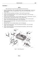
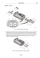
Measure clearance between rotor lobes and blower housing at (Figure 9, Item A) and
(Figure 9, Item B). Take measurements across entire length of each rotor lobe. Clearance
(Figure 9, Item B) must be 0.004 inch (0.102 mm) minimum and clearance (Figure 9, Item A) must be
0.010 inch (0.254 mm) minimum.
b.
Rotate gears until rotor lobes are at their closest position. Measure clearance (Figure 9, Item C)
between rotor lobes across entire length. Clearance must be 0.009 inch (0.229 mm) minimum.
c.
Measure clearance (Figure 9, Item D) between end of rotors and blower end plates. Push rotor toward
end plate being measured and hold at this position while obtaining measurement. For model
5063-5299, clearance must be 0.008 inch (0.20 mm) minimum at front end plate and 0.010 inch
(0.254 mm) minimum at rear end plate. For models 5063-5292, 5063-5293, and 5063-529L, clearance
must be 0.010 inch (0.254 mm) minimum at front end plate and 0.012 inch (0.305 mm) minimum at
rear end plate.
D
D
C
B
B
A
A
C
MAINT_298
Figure 9.
Blower Rotor Lobe Clearance.
TM 9-2815-205-24
0085
0085-12
Back to Top

