TM-9-2815-205-24 - Page 595 of 856
ASSEMBLY - Continued
19.
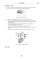
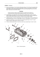
Remove four bolts (Figure 10, Item 44) and four flat washers (Figure 10, Item 43) used to temporarily fasten
front end plate to blower housing. Install new gasket (Figure 10, Item 22), cover (Figure 10, Item 23), two
spacers (Figure 10, Item 24), two plates (Figure 10, Item 2), and six screws (Figure 10, Item 1) on front of
blower. Torque bolts to 20–25 lb-ft (27–34 N·m).
CAUTION
Excessive protrusion of blower housing with respect to end plate will cause distortion of
housing when blower hold-down bolts are tightened and result in rotor to housing contact.
20.
Using depth gage, check relationship of front and rear blower end plates (Figure 10, Items 7 and 30) to
bottom of blower housing (Figure 10, Item 28). Protrusion of blower housing with respect to end plate must
not be more than 0.001 inch (0.025 mm) above or 0.004 inch (0.102 mm) below end plate.
21.
Install spacer (Figure 10, Item 20), coupling (Figure 10, Item 19), retainer (Figure 10, Item 18), and four new
self-locking bolts (Figure 10, Item 17) on gear (Figure 10, Item 21). Torque bolts to 14–18 lb-ft (19–24 N·m).
22.
Install drive coupling (Figure 10, Item 10) and four new self-locking bolts (Figure 10, Item 11) on gear
(Figure 10, Item 12). Torque bolts to 8–10 lb-ft (11–14 N·m).
23.
If removed, install pipe plug (Figure 10, Item 32) into side of each end plate (Figure 10, Items 7 and 30).
7
1
10
11
12
32
17
18
19
24
23
22
20
21
2
44
43
32
28
30
MAINT_299
Figure 10.
Blower Assembly.
TM 9-2815-205-24
0085
0085-13
Back to Top


