TM-9-2815-205-24 - Page 603 of 856
ASSEMBLY - Continued
CAUTION
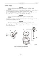
Do not cock or force metal seal rings (Figure 6, Item 22) in grooves. Ring is brittle and will
snap easily.
6.
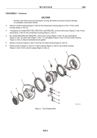
Install two new metal seal rings (Figure 6, Item 22) on thrust spacer (Figure 6, Item 23). Lubricate seal rings
with engine oil and gently insert thrust spacer assembly into backplate (Figure 6, Item 20).
7.
On models 5063–5392, 5063-5393, and 5063-539L, install backplate (Figure 6, Item 20) and four screws
(Figure 6, Item 19) on center housing. Torque bolts to 90–110 lb-in. (10.2–12.5 N·m).
CAUTION
Do not cock or force retaining ring (Figure 6, Item 18) in groove. Ring is brittle and will
snap easily.
8.
Fill piston ring groove with high vacuum silicone lubricant and install new retaining ring (Figure 6, Item 18)
on turbine wheel assembly (Figure 6, Item 16).
CAUTION
Do not scuff or scratch bearings when installing shaft or bearing will seize during operation.
9.
Lubricate turbine wheel assembly (Figure 6, Item 16) with engine oil. Position wheel shroud
(Figure 6, Item 17) against center housing (Figure 6, Item 2). Insert turbine wheel assembly through wheel
shroud and into center housing.
19
20
22
23
17
16
18
2
MAINT_306
Figure 6.
Turbo Center Turbine Shaft Assembly.
TM 9-2815-205-24
0086
0086-7
Back to Top

