TM-9-2815-205-24 - Page 587 of 856
DISASSEMBLY - Continued
18.
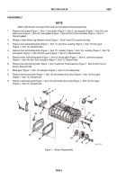
If necessary, remove oversize seal sleeve (Figure 4, Item 33) from each end of each blower rotors
(Figure 4, Items 9 and 8) using a cold chisel to split the sleeve. Discard sleeves.
8, 9
33
MAINT_293
Figure 4.
Blower Rotor Disassembly.
19.
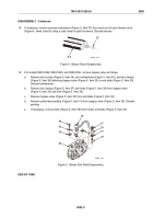
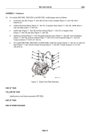
For models 5063-5392, 5063-5393, and 5063-539L, remove bypass valve as follows:
a.
Remove two screws (Figure 5, Item 34), two lockwashers (Figure 5, Item 40), and two clamps
(Figure 5, Item 36) fastening bypass valve (Figure 5, Item 35) to end plate (Figure 5, Item 30).
Discard lockwashers.
b.
Remove two clamps (Figure 5, Item 37) and hose (Figure 5, Item 38) from bypass valve
(Figure 5, Item 35) and tube (Figure 5, Item 39).
c.
Remove bypass valve (Figure 5, Item 35) from end plate (Figure 5, Item 30).
d.
Remove preformed packing (Figure 5, Item 41) from bypass valve (Figure 5, Item 35). Discard
packing.
e.
If necessary, remove tube (Figure 5, Item 39) from blower end plate (Figure 5, Item 30).
30
34
35
41
40
39
38
37
36
36
37
MAINT_294
Figure 5.
Blower End Plate Disassembly.
END OF TASK
TM 9-2815-205-24
0085
0085-5
Back to Top


