TM-9-2815-205-24 - Page 590 of 856
ASSEMBLY
NOTE
If rotor shafts have grooves from seal, install an oversize sleeve on the shaft. If an oversize
seal is installed, also install an oversize sleeve.
1.
Install oversize sleeve on blower rotor shaft as follows:
a.
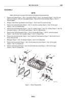
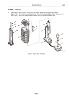
Position left rotor (Figure 6, Item 8) on wood blocks and install oversize sleeve (Figure 6, Item 33) over
blower rotor shaft (Figure 6, Item 46). Using blower sleeve installer (Figure 6, Item 42), press sleeve
until shoulder of installer contacts shaft. Repeat for opposite end rotor shaft.
b.
Repeat Step 1.a. for right blower rotor.
CAUTION
New standard size seals are Teflon coated and must be installed dry to ensure proper
sealing. Oversized seals are not Teflon coated and must be lubricated prior to installing to
ensure proper sealing.
NOTE
Identify rear end plate (Figure 6, Item 30) by governor lubrication oil hole (Figure 6, Item A)
drilled in outer face of plate. Install blower seals (Figure 6, Item 29) with lips dry.
2.
Install two new standard or oversize seals in each end plate as follows:
a.
Place front end plate (Figure 6, Item 7), seal counterbores up, on press.
b.
Lubricate outer diameter of seal (Figure 6, Item 29) with engine oil.
c.
Place seal (Figure 6, Item 29), lip facing down with part number on seal facing out, in counterbore.
Using blower seal installer (Figure 6, Item 45), press seal until shoulder of installer contacts end plate.
d.
Repeat Steps 2.b. – 2.c. for second seal (Figure 6, Item 29).
e.
Repeat Steps 2.a. – 2.d. for rear end plate (Figure 6, Item 30).
CAUTION
Sealant is required when assembling blower end plates to blower housing. Failure to apply
sealant may result in air leakage between blower housing and end plates, which may affect
engine performance.
NOTE
Blower end plate and blower housing mating surfaces must be thoroughly clean and free of
any grease, oil film, or cleaner residue. Clean the surfaces with cleaning solvent.
3.
Apply a thin, even coating of Teflon-based sealing compound from sealant kit over the entire end surfaces
of both ends of the blower housing. Wipe off any excess sealant from housing bore. Allow sealant to dry to
touch before assembling housing to end plates.
4.
Place front end plate (Figure 6, Item 7), inner face up, on two wooden blocks. Install right rotor
(Figure 6, Item 9) and left rotor (Figure 6, Item 8), splined shaft ends up, in end plate.
NOTE
Install blower housing in same orientation as match marked during removal for better rotor
to housing clearances.
5.
Install blower housing (Figure 6, Item 28) over rotors (Figure 6, Items 8 and 9).
TM 9-2815-205-24
0085
0085-8
Back to Top


