TM-9-2815-205-24 - Page 615 of 856
ASSEMBLY
1.
Governor cover procedures:
a.
If removed, press two pins (Figure 6, Item 12) in bottom of cover (Figure 6, Item 9) until flush to
0.005 inch (0.127 mm) below machined surface.
b.
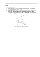
If bushings (Figure 5, Item 11) were removed, place governor cover (Figure 5, Item 9), inner face
down, in press. Start bushing straight into bore, numbered side up. Place bearing installer
(Figure 5, Item 71) in bushing and press until shoulder of installer contacts cover. Invert cover and
install second bushing (Figure 5, Item 11) in same manner.
9
11
71
MAINT_314
Figure 5.
Governor Cover Bushing Replacement.
TM 9-2815-205-24
0087
0087-7
Back to Top


