TM-9-2815-205-24 - Page 621 of 856
ASSEMBLY - Continued
q.
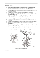
Apply sealing compound around edge of new expansion plug (Figure 10, Item 45) and tap in place in
governor housing (Figure 10, Item 43).
r.
If removed, apply sealing compound around edge of new plug (Figure 10, Item 64) and tap in place in
governor housing (Figure 10, Item 43).
s.
Install flat washer (Figure 10, Item 42) and special screw (Figure 10, Item 41) against governor
bearing (Figure 10, Item 44).
t.
If removed, press pin (Figure 10, Item 33) in differential lever (Figure 10, Item 36) until pin bottoms out
on shoulder.
u.
Install differential lever (Figure 10, Item 36) assembly over pin (Figure 10, Item 40). Install flat washer
(Figure 10, Item 35) and retaining clip (Figure 10, Item 34) against assembly.
v.
Place first flat washer (Figure 10, Item 47) over grooved pin (Figure 10, Item 46). Pack roller bearings
(Figure 10, Item 49) with grease and install roller bearing and control link lever (Figure 10, Item 50)
assembly, tapered end of link pin holes down, over grooved pin. Place second flat washer
(Figure 10, Item 47) over grooved pin and install retaining clip (Figure 10, Item 32).
w.
Thread nut (Figure 10, Item 38) on buffer screw (Figure 10, Item 39). Place spring (Figure 10, Item 37)
in buffer screw and thread screw in side of governor housing (Figure 10, Item 43) until it extends
9/16–5/8 inch (14.28–15.87 mm) beyond housing.
32
33
34
35
46
45
44
43
42
40
39
38
36
49
50
64
47
47
41
37
MAINT_319
Figure 10.
Governor Housing Installation.
END OF TASK
TM 9-2815-205-24
0087
0087-13
Back to Top


