TM-9-2815-205-34 - Page 175 of 596
TM 9-2815-205-34
3-12.1 GLOW PLUGS, CONTROLLER AND HARNESS REPLACEMENT (MODEL 5063-539L)
(Cont)
b. Installation
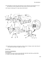
(1) Place mounting bracket (27) over front of
(2)
(3)
(4)
(5)
(6)
(7)
(8)
(9)
air inlet housing 35) and against upper
-
”
front cover (36). Position two spacers (34)
under mounting bracket and install two flat
washers (33), two lockwashers (32), and
two long screws (31) into top of bracket
and install two flat washers (30), two
lockwashers (29), and two short screws
(28) into front of bracket. Torque screws
(31) to 16-20 lb-ft (22-27 N•m) and screws
(28) to 46-50 lb-ft (62-68 N•m).
Secure glow plug controller (15) to
mounting bracket 27 with four flat
washers (25), two lockwashers (32), and
nuts (26) and two short screws (28).
Torque screws to 13-17 lb-ft (18-23 N•m).
If removed, install two clips (18) on each
side of glow plug harness (20).
Connect glow plug harness (20) to right
side of glow plug controller (15). Tighten
securely.
Install three glow plugs (22) in left cylinder
head. Torque plugs to 132-156 lb-in (15-18
N•m).
CAUTION
Glow plug harness leads are
identified with location as to
right or left bank. Correct
installation of
wires
is
necessary for prope r
diagnostics to aid in locating a
failed glow plug,
Install three ends (21) of glow plug
harness (20) to corresponding glow plug
(22) locations in left cylinder head.
Secure glow plug harness (20) to two
brackets (19) on left cylinder head with two
bolts (16) and two nuts (17). Torque bolts
to 30-35 lb-ft (41-47 N•m).
Repeat steps (4) through (7) above for
opposite side.
Connect glow plug power harness (1) to
left side of glow plug controller (15).
3-48.2
Change 1
Back to Top

