TM-9-2815-205-34 - Page 183 of 596
TM 9-2815-205-34
3-14. THERMOSTAT HOUSING AND CROSSOVER TUBE REPLACEMENT (ALL EXCEPT MODEL
5063-5393) (Cont)
(4) Inspect thermostat as follows:
(a) Immerse thermostat in container of water. Do not allow it to touch bottom of container.
NOT E
On
models
5063-5299,
5063-5395, 5063-5398, and
5063-539F, thermostat valve
should start opening a t
162-167°F (72-75°C). Valve
should be fully open at 182°F
(83°C).
On model 5063-5392, thermo-
stat valve should start opening
at 177-182°F (80-83°C). Valve
should be fully open at 197°F
(92°C).
(b) Agitate water to maintain an even temperature throughout container. As water is heated,
thermostat valve should begin to open. Allow at least 10 minutes for thermostat to react.
(c) Replace thermostat not meeting this requirement.
c. Installation
(1)
(2)
(3)
(4)
(5)
(6)
(7)
3-54
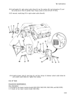
Install gasket (23), left coolant outlet elbow (5), two flat washers (22), two Iockwashers (21),
and two screws (20) on front of left cylinder head. Torque screws to 30-35 Ib-ft (41-47 N-m).
For models 5063-5299 and 5063-5392: if removed, install two plugs (24) in side of left coolant
outlet elbow (5).
Using seal installer and handle, press seal (17) in thermostat housing cover (14). Position seal
with lip facing toward inside of thermostat housing cover.
Install thermostat (16) into thermostat housing cover (14).
Install gasket (15), thermostat housing cover (14), four flat washers (13), four Iockwashers (12),
and four screws (11) on left coolant outlet elbow (5). Torque screws to 30-35 Ib-ft (41-47 N
.
m).
For models 5063-5299 and 5063-5392: if removed, install plug (19) in top of thermostat
housing cover (14).
Install drain cock (18) in bottom of thermostat housing cover (14).
Back to Top


