TM-9-2815-205-34 - Page 401 of 596
TM 9-2815-205-34
WARNING
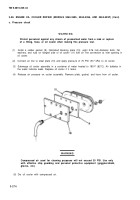
Compressed air used for cleaning purposes will not exceed 30 PSI. Use only
with effective chip guarding and personal protective equipment (goggles/shield,
gloves, etc.)
(e) Dry oil cooler with compressed air.
d. Assembly
(1)
(2)
•
•
(a)
(b)
(c)
I
(
Engine oil cooler
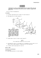
If removed, install pipe plug
bottom of oil cooler housing
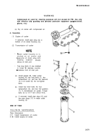
Transmission oil cooler
(12) in
(13).
Water outlet housing is in-
stalled on oil cooler end
opposite oil drain plug with
housing
reservoir
directly
above oil inlet port.
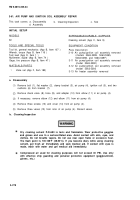
Two long bolts (1) are installed
in holes 90 degrees counter-
clockwise from oil inlet port.
Install gasket (8), water outlet
housing (4), two long bolts (1), two
Iockwashers (2), and two flat washers
(3) in oil cooler (9). Do not tighten
bolts.
Install four short bolts (5), four
Iockwashers (6), and four flat washers
(7), in transmission oil cooler. Torque
bolts (5) to 13-17 Ib-ft (18-23 N-m).
If removed, install pipe plug (10) and
two pipe plugs (11) in water outlet
housing (4).
END OF TASK
FOLLOW-ON MAINTENANCE
Para
2-4
2-18
Description
Install transmission oil cooler.
Install engine oil cooler.
3-271
Back to Top


