TM-9-2815-225-34-P - Page 232 of 736
TM 9-2815-225-34&P
0023 00
0023 00-2
OIL PUMP (Contd)
NOTE
This work package is divided into sections, Big Cam I and Big
Cam III engines.
BIG CAM I
Disassembly
1.
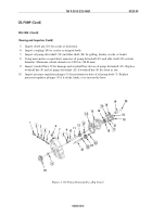
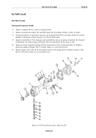
Using gear puller, remove oil pump drive gear (25) from oil pump driveshaft (11).
2.
Remove woodruff key (9) from oil pump driveshaft (11).
3.
Remove snapring (20) and coupling (19) from oil pump driveshaft (11).
4.
Remove connector (16) from oil pump housing (15).
5.
Remove pipe plug (6) from oil pump body (7).
WARNING
Oil pump pressure regulator spring is under tension. Remove
oil pump pressure regulator slowly and wear proper eye
protection. Failure to do so may result in injury to personnel.
6.
Remove screw (1), lockplate (2), retaining yoke (3), pressure regulator spring (4), and plunger (5)
from oil pump body (7). Discard lockplate (2) and pressure regulator spring (4).
7.
Remove six screws (18), three lockwashers (17), and two washers (21) securing oil pump housing
(15) to oil pump body (7). Discard lockwashers (17).
8.
Remove oil pump housing (15) and gasket (14) from oil pump body (7). Discard gasket (14).
9.
Remove dowel pin (10) from oil pump body (7).
10.
Using press, remove oil pump driveshaft (11), with oil pumping gear (12) attached, from oil pump
body (7).
11.
Using press, remove oil pump driveshaft (11) from oil pumping gear (12).
12.
Remove idler gear (23) from idler shaft (24).
13.
Using press, remove idler shaft (24) from oil pump body (7).
14.
Using press and mandrel, remove bushing (13) from oil pump housing (15). Discard bushing (13).
15.
Using press and mandrel, remove two bushings (8) from oil pump body (7). Discard bushings (8).
16.
Using press and mandrel, remove bushings (22) from idler gear (23). Discard bushing (24).
Cleaning and Inspection
1.
For general parts cleaning information, refer to CLEANING, WP 0051 00.
2.
For general parts inspection information, refer to INSPECTION, WP 0051 00.
NOTE
Replace any part that does not pass visual inspection or is
outside specified wear limits.
3.
Inspect oil pumping gear (12) and idler gear (23) for cracks and stripped or chipped teeth.
4.
Inspect oil pump body (7) and oil pump housing (15), for cracks and stripped or elongated
threaded bolt holes. Repair all stripped or elongated threaded bolt holes.
Back to Top


