TM-9-2815-225-34-P - Page 238 of 736
TM 9-2815-225-34&P
0023 00
0023 00-8
OIL PUMP (Contd)
BIG CAM III (Contd)
Assembly
NOTE
Lubricate all parts with OE/HDO 10 lubricating oil before
assembly.
New bushings must be line reamed to size before oil pump
assembly.
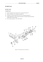
1.
Using press and mandrel, install two new bushings (5) and (19) in idler gear (20). Do not press
bushing (19) more than 0.020 in. (0.508 mm) below top surface of idler gear (20). Using drill press
and reamer, line-ream inside diameter of bushing (19) to 0.8767–0.8777 in. (22.268–22.293 mm).
2.
Using press and mandrel, install two new bushings (2) in oil pump body (3). Do not press
bushings (2) more than 0.020 in. (0.508 mm) below top surfaces of oil pump body (3). Using drill
press and reamer, line-ream inside diameter of bushings (2) to 0.8767–0.8777 in.
(22.268–22.293 mm).
3.
Using press and mandrel, install new bushing (12) in oil pump cover (14). Do not press bushing
(12) more than 0.020 in. (0.508 mm) below top surfaces of oil pump cover (14). Using drill press
and reamer, line-ream inside diameter of bushing (12) to 0.8767–0.8777 in. (22.268–22.293 mm).
4.
Using press, install oil pumping gear (11) on oil pump driveshaft (10).
5.
Using press, install oil pump driveshaft (10) with oil pumping gear (11) attached, in oil pump
body (3) until oil pump driveshaft (10) protrudes 1.035–1.055 in. (2.629–2.680 cm) above oil pump
body (3).
6.
Using press, install idler shaft (21) with large end facing up, in oil pump body (3) until large end
protrudes 0.9375–1.0 in. (23.81–25.40 mm) above oil pump body (3).
7.
Install idler gear (20) on idler shaft (21).
8.
Using feeler gauge, check oil pumping gear (11) to oil pump body (3) clearance. Clearance should
be 0.060–0.070 in. (1.52–1.78 mm). Remove and install oil pumping gear (11) until correct
clearance is obtained.
9.
Install new bypass spring (4), washer (5), bypass valve disc (6), and bypass valve seat (7) in oil
pump body (3).
10.
Install dowel pin (9) in oil pump body (3).
11.
Install new gasket (13) and oil pump cover (14) on oil pump body (3) with seven screws (18).
Tighten screws (18) 35 lb-ft (48 N
•
m).
12.
Install two new O-rings (24) on retainer (25).
WARNING
Oil pump pressure regulator spring is under tension. Install
oil pump pressure regulator screw slowly and wear proper eye
protection. Failure to do so may result in injury to personnel.
13.
Install plunger (22), new pressure regulator spring (23), retainer (25), washer (26), and screw (27)
in oil pump body (3).
Back to Top

