TM-9-2815-225-34-P - Page 422 of 736
TM 9-2815-225-34&P
0046 00
0046 00-10
REMOVING ENGINE FROM MAINTENANCE STAND (Contd)
23.
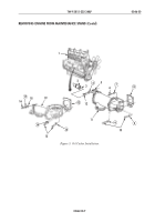
Apply antiseize compound to threads of studs (2) and install new gasket (3) on exhaust manifold
studs (2).
24.
Install turbocharger (5) on exhaust manifold (1) with four nuts (4). Tighten nuts (4)
20–25 lb-ft (27–34 N
•
m).
NOTE
Perform step 25 for Big Cam I only.
25.
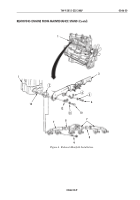
Install oil return tube (9) and hose (12) on elbows (8) and (16) with two clamps (11) and (13).
Tighten clamps (11) and (13) 35–45 lb-ft (48–61 N
•
m).
NOTE
Perform steps 26 and 27 on Big Cam III only.
26.
Install oil return tube (10) and hose (12) on elbows (6) and (16) with two clamps (11) and (13).
Tighten clamps (11) and (13) 35–45 lb-ft (48–61 N
•
m).
27.
Install oil return tube (7) and two bushings (14) and (17) on filter head (15) and oil return tube
(10). Tighten fittings on oil return tube (7) 50–60 lb-ft (68–81 N
•
m).
28.
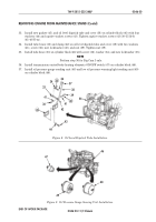
Install oil supply hose (19) on adapter (18) and elbow (22). Tighten fittings on oil supply hose (19)
50–60 lb-ft (68–81 N
•
m).
29.
Install clamp (20) and screw (21) on turbocharger (5). Tighten screw (21) 14 lb-ft (19 N
•
m).
30.
Install four bolts (25), washers (26), turbocharger air crossover (27), clamps (28) and (30), new
hose (29), and new gasket (32) on aftercooler cover (31).
31.
Install hose (23) and fitting (24) on turbocharger air crossover (27).
32.
Tighten clamps (28) and (30) retaining turbocharger air crossover (27) and hose (29) to
turbocharger (5).
Figure 5. Turbocharger Installation
Figure 6. Turbocharger Oil Supply
Hose Installation.
Figure 7. Turbocharger Air
Crossover Installation.
1
2
3
4
5
6
7
8
9
10
12
13
14
15
16
17
11
5
18
19
20
21
22
23
31
24
25
26
27
28
29
30
5
32
Back to Top

