TB-9-2320-280-35-12 - Page 36 of 162
TB 9-2320-280-35-12
5-12
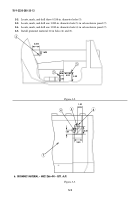
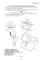
1. LOCKWASHER – MS35338-44 – QTY. 3
2. WASHER – 2436161 – QTY. 4
3. CAPSCREW – B1821BH025C100N – QTY. 3
4. CPU ISOLATION KIT – 872826-2 – QTY. 1
6. CPU – 881292-1 – QTY. 1
11. CAPSCREW – B1821BH025C125N – QTY. 1
12. LOCKWASHER – MS45904-68 – QTY. 2
13. CPU GROUND STRAP
• BRAIDED WIRE – AA59569F30T0375 – QTY. A/R
• TERMINAL LUG – MS20659-141 – QTY. 2
Section VI. FBCB2 COMPONENTS INSTALLATION
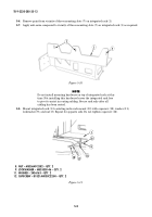
NOTE
SINCGARS model AN/VRC-92F shown.
6-1.
Remove paint from vicinity of holes (8) on integrated rack (7) and on both sides from vicinity of
corresponding holes (10) on CPU isolation kit (4). Apply anti-seize compound as required.
6-2.
Install CPU isolation kit (4) on integrated rack (7) with three capscrews (3), washers (2), and
lockwashers (1), leaving open holes (8) and (10).
6-3.
Install keyboard (9) in keyboard slot of integrated rack (7).
6-4.
Install CPU (6) on CPU isolation kit (4) with two existing fastener guards (5).
6-5.
Fabricate ground strap (13) from 8.00-in. length of braided wire and two terminal lugs.
6-6.
Install ground strap (13) on CPU ground stud (17) with existing washer (14), lockwasher (15), and
wingnut (16).
6-7.
Install ground strap (13) on CPU isolation kit (4) and integrated rack (7), with capscrew (11),
washer (2), and two lockwashers (12).
1
2
3
4
5
5
6
6
4
10
10
11
2
13
10
14
15
16
17
7
12
Figure 5-17.
8
9
Change 1
Back to Top

