TB-9-3950-253-13-P
PALLETIZED LOAD SYSTEM TRUCK, M1075 and M1075A1 (PLS) AND HEAVY EXPANDED MOBILITY TACTICAL TRUCK, M1120, M1120A2, AND M1120A4 (HEMTT), ENHANCED CONTAINER HANDLING UNIT (E-CHU)
TECHNICAL BULLETIN; OPERATOR AND FIELD MAINTENANCE, INSTALLATION INSTRUCTIONS, AND REPAIR PARTS AND SPECIAL TOOLS LIST
JULY 2009
TB-9-3950-253-13-P - Page 520 of 704
TB 9-3950-253-13&P
Change 1
0052-10
0052
HEMTT STOWAGE ASSEMBLY INSTALLATION – CONTINUED
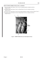
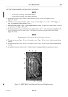
17. Route four upper hoses (Figure 8, Item 2) in front of stowage assembly to hydraulic control box
(Figure 8, Item 1).
18. Install four upper hoses (Figure 8, Item 2) on fittings (Figure 8, Item 3) on hydraulic control box
(Figure 8, Item 1).
19. Route four lower hoses (Figure 8, Item 4) under stowage assembly to hydraulic control box (Figure 8, Item 1).
20. Install four lower hoses (Figure 8, Item 4) on fittings (Figure 8, Item 5) on hydraulic control box
(Figure 8, Item 1).
Figure 8.
HEMTT M1120A4 Route and Install Hydraulic Hoses.
052
Back to Top


