TB-9-3950-253-13-P
PALLETIZED LOAD SYSTEM TRUCK, M1075 and M1075A1 (PLS) AND HEAVY EXPANDED MOBILITY TACTICAL TRUCK, M1120, M1120A2, AND M1120A4 (HEMTT), ENHANCED CONTAINER HANDLING UNIT (E-CHU)
TECHNICAL BULLETIN; OPERATOR AND FIELD MAINTENANCE, INSTALLATION INSTRUCTIONS, AND REPAIR PARTS AND SPECIAL TOOLS LIST
JULY 2009
TB-9-3950-253-13-P - Page 521 of 704
0052-11
Change 1
TB 9-3950-253-13&P
0052
HEMTT STOWAGE ASSEMBLY INSTALLATION – CONTINUED
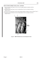
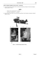
21. Loosen three locking pins (Figure 9, Item 1) and remove manifold cover (Figure 9, Item 2) from stowage
assembly (Figure 9, Item 6).
NOTE
•
Pressure hose is marked with “P” on solenoid.
•
Relief hose is marked with “T” on solenoid.
22. Identify pressure hose (Figure 9, Item 4) and relief hose (Figure 9, Item 3) based on markings on manifold
(Figure 9, Item 5).
Figure 9.
Identify Stowage Hydraulic Hoses.
052
1
2
3
4
5
6
Back to Top

