TB-9-3950-253-13-P
PALLETIZED LOAD SYSTEM TRUCK, M1075 and M1075A1 (PLS) AND HEAVY EXPANDED MOBILITY TACTICAL TRUCK, M1120, M1120A2, AND M1120A4 (HEMTT), ENHANCED CONTAINER HANDLING UNIT (E-CHU)
TECHNICAL BULLETIN; OPERATOR AND FIELD MAINTENANCE, INSTALLATION INSTRUCTIONS, AND REPAIR PARTS AND SPECIAL TOOLS LIST
JULY 2009
TB-9-3950-253-13-P - Page 523 of 704
0052-13
Change 1
TB 9-3950-253-13&P
0052
HEMTT STOWAGE ASSEMBLY INSTALLATION – CONTINUED
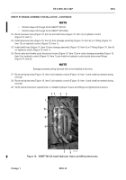
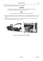
30. Route pressure hose (Figure 11, Item 4) and relief hose (Figure 11, Item 5) to hydraulic control
(Figure 11, Item 1).
31. Install pressure hose (Figure 11, Item 4) on T-fitting (Figure 11, Item 9) on hydraulic control (Figure 11, Item 1).
32. Install relief hose (Figure 11, Item 5) on T-fitting (Figure 11, Item 6) on hydraulic control (Figure 11, Item 1).
33. Route male and female quick disconnect hoses (Figure 11, Item 8) from under stowage assembly to hydraulic
control (Figure 11, Item 1) and install on hydraulic control quick disconnect fittings (Figure 11, Item 7).
NOTE
Stowage assembly wiring harness will not be installed at this time.
34. Route wiring harness (Figure 11, Item 2) to hydraulic control (Figure 11, Item 1) and install as marked during
removal.
35. Route wiring harness (Figure 11, Item 3) to hydraulic control (Figure 11, Item 1) and install as marked during
removal.
36. Verify that all loosened, repositioned, or installed hydraulic hoses and fittings are tightened and secure.
Figure 11.
HEMTT M1120A4 Install Hydraulic Hoses and Wiring Harnesses.
052
Back to Top


