TM-5-2350-378-24-P - Page 565 of 790
TM 5--2350--378--24&P
0030 00--4
REPLACE WIRING HARNESS W3 -- Continued
0030 00
REMOVAL -- CONTINUED
7.
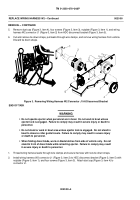
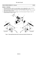
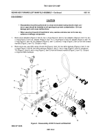
Remove wiring harness W3 connector P32 (Figure 3, item 3) from transducer T9 (Figure 3, item 2) at left
sprung stop cylinder (Figure 3, item 1).
8.
Remove wiring harness W3 connector P33 (Figure 3, item 6) from transducer T8 (Figure 3, item 5) at right
sprung stop cylinder (Figure 3, item 4).
9.
Remove tie down straps, open cable clamps, and remove wiring harness W3 from vehicle. Discard tie down
straps.
END OF TASK
INSTALLATION
WARNING
Ensure that vehicle power is off and battery disconnected. Remove all jewelry, such
as rings, dog tags, bracelets, etc. If jewelry or disconnected battery ground cable
contacts battery positive terminal, a direct short will result, causing instant heating of
tools, tool damage, battery damage, or battery explosion. Failure to comply may
result in severe injury or death.
1.
Position wiring harness W3 in vehicle, secure in cable clamps, and secure with new tie down straps.
2.
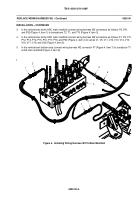
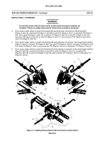
Connect wiring harness W3 connector P33 (Figure 3, item 6) to transducer T8 (Figure 3, item 5) at right
sprung stop cylinder (Figure 3, item 4).
3.
Connect wiring harness W3 connector P32 (Figure 3, item 3) to transducer T9 (Figure 3, item 2) at left
sprung stop cylinder (Figure 3, item 1).
Figure 3. Installing Wiring Harness W3 At Actuator Area
Back to Top


