TM-5-2350-378-24-P - Page 566 of 790
TM 5--2350--378--24&P
0030 00--5
REPLACE WIRING HARNESS W3 -- Continued
0030 00
INSTALLATION -- CONTINUED
WARNING
Do not work under vehicle unless hull is on jack stands and apron lockpins are
installed. Failure to comply may result in severe injury or death to personnel.
4.
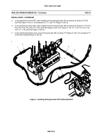
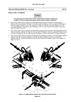
From access under vehicle, connect the following W3 wiring harness connectors to the aft manifold
(Figure 4, item 12): connector P4 (Figure 4, item 25) to valve V4 (Figure 4, item 11), connector P6 (Figure 4,
item 14) to valve V6 (Figure 4, item 13), connector P7 (Figure 4, item 16) to valve P7 (Figure 4, item 15),
connector P8 (Figure 4, item 18) to valve V8 (Figure 4, item 17), and connector P18 (Figure 4, item 24) to
valve V18 (Figure 4, item 10).
5.
From access under vehicle, connect the following W3 wiring harness connectors to the forward left manifold
(Figure 4, item 9): connector P3 (Figure 4, item 7) to valve V3 (Figure 4, item 8), connector P9 (Figure 4, item
6) to valve V9 (Figure 4, item 5), and connector P30 (Figure 4, item 4) to transducer T10 (Figure 4, item 3).
6.
From access under vehicle connect the following W3 wiring harness connectors to the forward right manifold
(Figure 5, item 23): connector P2 (Figure 5, item 20) to valve V2 (Figure 5, item 21), connector P10
(Figure 5, item 19) to valve V10 (Figure 5, item 22), and connector P11 (Figure 5, item 1) to transducer T11
(Figure 5, item 2).
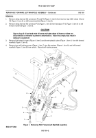
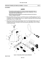
Figure 4. Installing Wiring Harness W3 Connections Under Vehicle
Back to Top

