TM-9-2320-209-20-3-1 - Page 464 of 830
TM 9-2320-209-20-3-1
c.
Replacement.
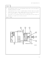
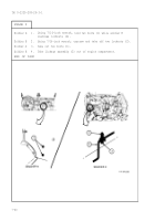
FRAME 1
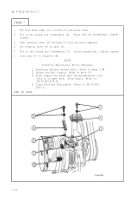
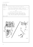
1.
Put generator regulator (1) on shock mount assembly (2) as shown.
2.
Put on four lockwashers (3). Using 1/2-inch wrench, screw on and tighten
four nuts (4).
3.
Aline slot in generator cable connector (5) with key in receptacle (6). Plug
in connector and screw on tight.
4.
Aline slot in chassis wiring connector (7) with key in receptacle (8). Plug in
connector and screw on tight.
NOTE
Follow-on Maintenance Action Required:
1.
Do polarization procedure. Refer to para 7-3.
2. Reconnect battery ground cable. Refer to para 7-58.
3.
Start engine and check that battery-generator
indicator is in green area. Stop engine. Refer to
TM 9-2320-209-10.
4.
Close hood and left side panel. Refer to
TM 9-2320-209-10.
END OF TASK
7-28
Back to Top

