TM-9-2320-273-34 - Page 144 of 801
TM 9-2320-273-34
TA 074015
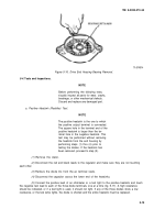
Figure 5-17. Positive Heatsink Test.
(6)
Connect the negative test lead to the positive heatsink and touch the positive lead to each of
the three diode terminals, one at a time (fig. 5-17). A low resistance should be indicated. (If a test light is
used, it should light.) If a high resistance is obtained, or if test light fails to light, an open diode is indi-
cated and the entire heatsink assembly must be replaced.
b. Negative Heatsink (Rectifier) Test.
NOTE
The negative heatsink is the one to which
the negative output terminal is connected.
The square hole in the terminal end of the
negative heatsink is smaller than the ter-
minal hole in the positive heatsink. If this
test is performed without removing the
heatsink from the end housing, verify that
steps (1) thru (4) in
a,
above have been
performed.
(1)
Connect the negative test lead to the negative heatsink and touch the positive test lead to
each of the three diode terminals, one at a time (fig. 5-18). If a low resistance reading is obtained, or if
test lamp lights, the diode is shorted and the entire heatsink must be replaced.
(2)
Connect the positive test lead to the negative heatsink and touch the positive lead to each
of the three diode terminals, one at a time (fig. 5-18). A low resistance reading should be obtained, and if
a test light is used, the lamp should light. If high resistance is indicated or the lamp does not light, it is
open and the entire heatsink assembly must be replaced.
5-16
Back to Top


