TM-9-2320-273-34 - Page 152 of 801
TM 9-2320-273-34
(2)
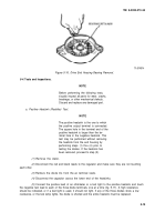
Install the heatsinks in the end housing. Be sure that the upper and lower insulating
washers are in their proper locations (fig. 5-31). Install, but do not tighten, the lower heatsink retaining
screws, Iockwashers, guardwashers, and insulating washers.
TA 074011
Figure 5-31. Correct Heatsink Mounting Assembly.
(3)
Install terminal bolts and regulator lead wires on the heatsinks. The red wire goes on the
positive heatsink (large square hole) and the black wire goes on the negative heatsink. Be sure that mating
surfaces of the heatsinks, terminals, and bolts are clean and free of paint to ensure a good electrical
connection.
(4)
Install two insulating bushings on each terminal stud and install the regulator housing,
Route the red and black leads through the cutaway section of the end housing. Install and tighten the
nuts on the terminal bolts.
(5)
Tighten the lower heatsink screws and check all leads for proper routing, being sure that no
lead is pinched under a heatsink.
(6)
Install and connect the capacitor.
(7)
Install the stator on the end housing; then connect the stator leads with the terminal nuts.
Temporarily install the three throughbolts to aline the stator and end housing,
When installing the end bearing in the fol-
lowing step, press only on the outer race
to avoid transmitting force through the
bearing balls and damaging the bearing.
(8)
Press the bearing into the drive end housing. Install the bearing retainer and four screws.
5-24
CAUTIO N
Back to Top


