TM-9-2320-273-34 - Page 153 of 801
TM9-2320-273-34
In the following step, use a sleeve around
the shaft to press on the inner race to
avoid damaging the bearing.
(9) press the drive end housing and bearing onto the rotor shaft.
(10) Remove the three throughbolts from the stator and end housing. Install the rotor and
drive end housing into the stator and slipring end housing, being sure to line up the mounting ears.
(11) Reinstall the three throughbolts and self-locking nuts. Torque to 50-60 lb-in (6-7 N-m).
Place a small amount of grease in the end housing and install the metal dust cap by tapping it into place.
(12) Install the diode trio and three nuts.
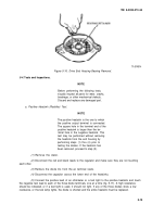
(13) Insert the outer brush and spring assembly into the housing and compress the brush spring,
using a small screwdriver. While holding the spring compressed, insert a pin through the hole in the rear
of the housing so that the spring is held in a compressed position. (A suitable pin can be made from a
paper clip.) Install and compress the remaining brush and spring assembly in the same manner, and by
pushing the pin farther into the housing as shown in figure 5-32.
Figure 5-32. Brush and Spring Installation.
TA 074029
(14) Attach the red and black leads to regulator (fig. 5-33). Attach the blue regulator lead to
the diode terminal by sliding the spade terminal under the head of the screw. Tighten the nut on the ter-
minal screw.
5-25
CAUTIO N
Back to Top


