TM-9-2320-273-34 - Page 146 of 801
TM 9-2320-273-34
TA 074018
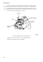
Figure 5-20. Capacitor Test.
e. Voltage Regu/ator Test.
The regulator contains devices connected in a way that parallel circuits
exist, making it impossible to electrically test each individual component as several will be in the circuit at
the same time.
For this reason, point-to-point resistance checks may be inconclusive or misleading. Refer to On-Vehicle
Testing, paragraph 5-2.
f. Rotor Test.
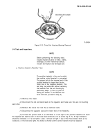
The rotor is tested for grounds and proper coil resistance as follows:
(1)
Connect
If a reading other than
replaced .
an ohmmeter between the rotor shaft and both sliprings, one at a time (fig. 5-21).
infinity is obtained, the rotor coil is grounded and the rotor must be removed and
Figure 5-27. Rotor Coil Test.
TA 074019
(2)
Check rotor coil resistance by connecting an ohmmeter across the two two sliprings, as shown
above. The resistance should be between 2.3 and 2.7 ohms.
5-18
Back to Top


