TM-9-2320-273-34 - Page 179 of 801
TM9-2320-273-34
CHAPTER 7
REPAIR OF TRANSMISSION
Section 1. INTRODUCTION
7-1. Description and Subassemblies.
a. General.
The transmission is a 16-speed forward mechanical drive transmission with two reverse
speeds. When starting the vehicle from a stop, the transmission input clutch automatically engages as the
engine rpm increases. The operator initiates the gear ratio selection by moving the lever of the ratio selector
in the cab. The shift in the transmission is controlled by air pressure acting on air cylinders in the transmis-
sion control unit and thereby shifting forks that move the appropriate gear couplings. (Details of the air
control system for the transmission and ratio selector are provided in TM 9-2320-273-20.) The shift is made
by the following method:
(1) The gear section of the transmission is temporarily disconnected from the engine and the
rear wheels of the truck.
(2) The rotation of the gear section is stopped.
(3) The gear couplings are moved for a new gear ratio.
(4) The gear section is given rotation again.
(5) The gear section of the transmission is connected to the engine and the rear wheels of the
truck again. The shift is now complete,
b. Subassemblies.
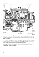
The major functional components of the transmission are shown in figure 7-1.
(1)
Input Clutch Group.
The input clutch group connects the engine flywheel to the transmis-
sion input shaft. The clutch group has several plates and disks that are cooled by oil. The input clutch is
engaged by oil pressure. This oil pressure is made by centrifugal force (the force of rotation) on the oil in
the clutch. The force of engagement increases as the engine rpm increases up to approximately 1000 rpm.
The input clutch is released by air pressure during a ratio change. When the clutch is engaged, power is
sent from the engine to the input shaft of the transmission.
(2) Input Brake Group.
The input brake group is connected to the input shaft of the transmis-
sion. The input brake works in combination with the output brake to stop the rotation of the gear group.
The input brake has a plate and two disks that are cooled by oil, Air pressure is used to engage the brake.
Spring force is used to release the brake. When the brake is engaged, the rotation of the gear group is
stopped.
(3) Gear Group.
The gear group is made up of two sections, with three countershafts in each
section. A center gear set is engaged with the three countershafts. The torque is divided and sent through
the three countershafts. Reverse idlers are on the front of the rear countershafts. All gears are constantly
engaged. Shift collars, moved by forks, cause the connection between the center shaft (with splines on the
outside) and the center gears (with splines on the inside), The result is the selection of the desired gear ratio
or transmission speed.
(4) Output Brake Group.
The output brake group is connected to the output shaft of the
transmission. The output brake works in combination with the input brake and stops the rotation of the
7-1
Back to Top

