TM-9-2320-273-34 - Page 169 of 801
TM9-2320-273-34
(11) Install washer
(12)
(13)
(14)
(15)
(16)
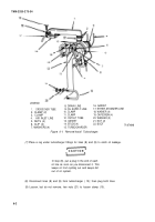
TA 074042
Figure 5-53. Solenoid Switch Installation.
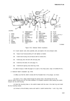
(26),
drive assembly
(25),
and washer (18) onto armature shaft.
Inspect nose housing bushing (21) and replace as needed.
Install nose housing (19) and secure with six screws (20).
Install plug (24), felt wick (22) and plug (23).
Install two felt wicks (12) and plugs (11).
Install brush opening cover band (fig. 5-43).
(17) Add 3-5 drops
of SAE 30-weight oil to each of the three wicks. (See LO 9-2320-273-12.)
d. Solenoid Switch Installation (fig. 5-53).
(1)
Make sure that the shaft is alined with the threaded hole in the plunger, as shown.
(2) Insert a 1/4-in. deep socket through the access hole in the terminal end of the
solenoid switch housing and turn the shaft clockwise 15 complete revolutions while pushing the switch
forward into the shift housing.
(3) Aline the mounting holes on the switch bracket with the ones in the field ring and install
the two mounting screws.
(4) Connect a 24-volt battery source and switch to switch terminal Nos. 1 and 4 (fig. 5-54).
5-41
Back to Top


