TM-9-2320-273-34 - Page 168 of 801
TM9-2320-273-34
TA 074045
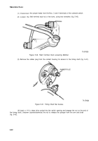
Figure 5-52. Field Coils Replacement.
(2)
Place them in the field ring and install the pole pieces.
Draw down the pole piece screws
evenly prior to final tightening.
(3)
Apply varnish to the coils, being careful not to get any on the inside surface of the pole
pieces.
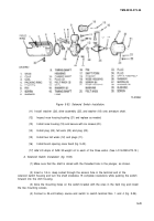
b. Commutator End Housing Bushing Replacement (fig. 5-49).
(1)
Press bushing (20) into the end housing from the inside until it is flush with the housing
core.
(2) Ream the bushing to a diameter of 0.875 in., ±0.001 in.
c.
Motor Assembly.
(1)
Install jumper screw (9), thru insulating washer (8), insulating bushing (6), sealing ring (7),
and commutator end housing (21). Then install insulating bushing (6), insulating washers (4) and (5), two
Iockwashers (24), washers (3), lead wire (2) and nut (1).
(2) Install four brush holder and spring assemblies (19). In each, install three insulating washers
(14), insulating bushing (13), Iockwasher (11), guard washer (12) and screw (10).
(3) Install brush holder jumper (17) with new packing.
(4) Install armature thru thrust washers (15) and (16) and insert into end housing bushing (20).
(5) Install armature thru field ring and install commutator end housing (21) with new packing
ring. Aline index marks and secure with four screws (23) and Iockwashers (22).
(6) Install eight brushes (18).
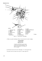
(7) Install
(8) Install
(9) Install
(10) Install
rubber boot (10, fig. 5-53) into timing shaft housing (9).
timing shaft link (15), shift fork (17), and pin (16), into timing shaft housing (9).
pin (6) and secure with washer (8), packing (5), and screw (7).
two washers (14) on armature shaft and install timing shaft housing (9) with new
packing ring (4). Aline index marks and assemble to field ring. Secure with five screws (27) and washers
(28).
5-40
Back to Top


