TM-9-2320-273-34 - Page 173 of 801
TM9-2320-273-34
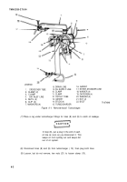
(10) Support turbocharger (15) and remove four nuts (5) and washers (7). Remove the turbo-
charger from four studs (14).
(11) Remove and discard gasket (13).
b. Installation.
(1) Install new gasket (13).
(2) Mount turbocharger (15) on studs (14) and secure with four washers (7) and nuts (5).
Tighten nuts to 57 Ib-ft (7-9 N-m) torque.
(3) Tighten two nuts (21) to secure clamp (10).
(4) Remove plug from line (8); then connect line to turbocharger. Tighten to 50 Ib-ft (68 N-m)
torque.
(5) Remove plug from line (9); then connect line to turbocharger. Tighten to 20 Ib-ft (27 N-m)
torque.
(6) Attach two clips (6) that secure oil supply line (9) to turbocharger. Fasten each clip with a
capscrew. Tighten to 5-7 Ib-ft (7-9 N-m) torque.
(7) Connect air inlet line (4) and outlet tube (12) to turbocharger. Tighten clamps (3) and
(11) to 30-35 lb-in (3-4 N-m) torque.
(8) Install new gasket (16).
(9) Mount crossover tube (1) with attached boot (22) on turbocharger and gasket (16).
Secure with four washers (18) and capscrews (19).
(10) Tighten clamps (2) to 30-35 lb-in (3-4 N-m).
(11) Connect ether atomizer line (17) to turbocharger.
c. Leak Check.
(1) Start up engine. (Refer to TM 9-2320-273-10.)
During normal operation, the turbocharger and
outlet pipe can become very hot. Be careful
not to touch these components with your
bare hands. These components may be hot
enough to cause severe burns.
(2) Check for oil and air leaks.
6-3. Accessory Drive Pulley.
a. Removal.
(1)
Remove fan. (Refer to TM 9-2320273-20.)
(2) Remove idler belt. (Refer to TM 9-2320273-20.)
6-3
WARNIN G
Back to Top


