TM-9-2320-273-34 - Page 456 of 801
TM 9-2320-273-34
(5)
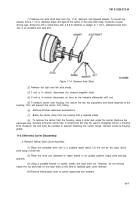
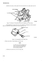
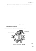
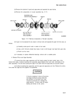
Remove the pump oil driven gears from their shaft within the oil pump cavity (fig.11-8).
Figure 11-8. Remove Oil Pump Relief Valve Cover Assembly and Oil Pump Gears.
(6)
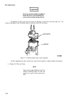
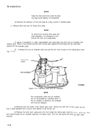
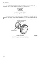
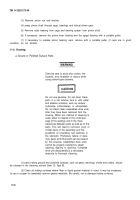
Disassemble the oil pump relief valve cover assembly by unthreading the hollow capscrew
(plug) and removing the spring and ball from the cover cavity (fig. 11-9).
Figure 11-9. Disassemble Oil Pump Relief Valve.
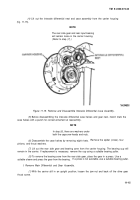
c. Remove Input Shaft, Forward Bearing, and Shift Collar.
NOTE
To remove the interaxle differential shift
collar, it is necessary to disassemble the
input shaft from the helical gear cover.
Use the following procedure.
(1)
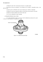
Remove the input yoke nut from the input shaft.
11-10
.
Back to Top


