TM-9-2320-273-34 - Page 463 of 801
TM 9-2320-273-34
(2)
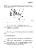
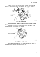
Remove the Iockwire (if used) and capscrews and separate the case halves.
(3)
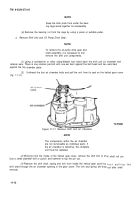
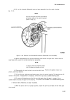
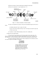
Remove the components of no-spin assembly (fig. 11-17).
Figure 11-17. Remove Components of No-Spin Assembly.
(4)
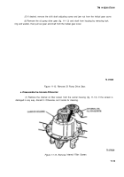
If gear is to be replaced for any reason, remove rivets and separate the gear from the case, as
follows:
(a)
Carefully center-punch rivets in center of the head.
(b)
Use a drill 1/32-inch smaller than body of rivet to drill through rivet head from gear side.
(c)
Punch out the rivets.
(s)
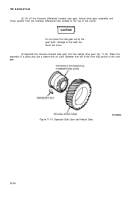
If necessary to replace differential bearings, remove with a suitable puller.
h. Remove Pinion and Cage Assembly.
(7)
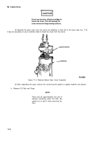
Loosen the pinion cage capscrews until the heads contact the back (under) face of the
helical driven gear. Continue loosening the capscrews approximately three turns each, alternating to the
other capscrews. This will avoid cocking the cage in the carrier while the capscrews act as puller screws.
(2)
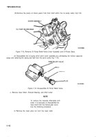
Continue loosening the capscrews until the cage and capscrews are free. Remove the shims
from under the cage and wire together for reassembly.
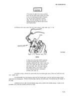
It may be necessary to tap out the pinion
and cage assembly by using a brass bar
and hammer on the pinion end. Care
should be exercised not to damage the
spigot bearing.
In either case, the spigot
bearing will remain on the. pinion.
11-17
CAUTION
Back to Top

