TM-9-2320-273-34 - Page 458 of 801
TM 9-2320-273-34
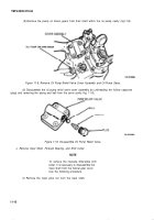
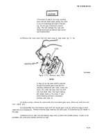
d.
NOTE
Keep the shim pack from under the bear-
ing cage wired together for reassembly.
(6)
Remove the bearing
CUP
from the cage by using a press or suitable puller.
Remove Shift Unit and Oil Pump Drive Gear.
NOTE
To remove the oil pump drive gear and
shaft assembly, it is necessary to first
remove the shift unit components.
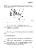
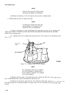
(1)
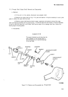
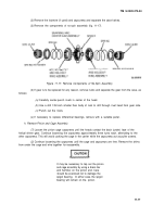
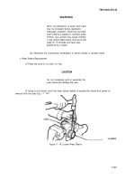
Using a screwdriver or other sharp-bladed tool: bend back the shift unit air chamber bolt
—.
retainer ears. There is one retainer per bolt with one ear bent against the bolt head and two ears bent
against the top
(2)
(fig. 11-11).
chamber plate,
Unthread the four air chamber bolts and pull the unit from its seat on the helical gear cover
Figure 11-11. Remove Shift Unit Air Chamber.
NOTE
The components within the air chamber
are not serviceable as individual parts. If
the air chamber is defective, the complete
unit must be replaced.
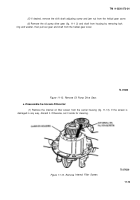
(3)
Working from the inside of the helical gear cover, remove the shift fork to sh
Use a small diameter drift or punch and hammer to tap the pin out.
(4)
Remove the shift shaft, spring and fork from inside the helical gear cover by
shift shaft through the air chamber opening in the gear cover. The fork and spring will drop
removal.
ift shaft roll pin.
first pulling the
out after shaft
11-12
Back to Top

