TM-9-2320-273-34 - Page 490 of 801
TM 9-2320-273-34
(5)
A
S
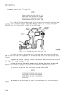
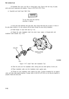
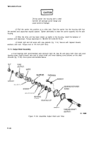
the helical gear cover is lowered onto the carrier, make certain the input shaft alines
with the bore through the interaxle differential; continue to lower the cover onto the carrier. As the input
shaft enters the interaxle differential, it may be necessary to index the shaft through the splines of the
spider (cross).
(6)
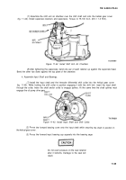
With the gear cover in position on the carrier, assemble the gear cover-to-carrier capscrews
and washers and torque capscrews to 85-115 Ib-ft (1 15-156 N•m).
o.
Adjust Input Bearing End Play.
NOTE
If original input shaft forward bearing is
installed with shim pack (para 11-9k (5),
tighten yoke nut enough to eliminate any
play between the yoke and bearing; then
proceed to step
(5).
(1)
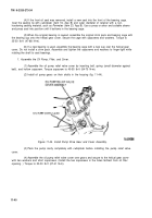
With the forward input bearing in place and the bearing cage assembled finger-tight on the
helical gear cover with no shim pack, measure the gap between the bearing cover and helical gear cover
using a feeler gage.
(2)
Add approximately 0.005 inch (0.127 mm) to measurement figure of gap. Add this
amount of shims under the bearing cover,
NOTE
Use a minimum of three shims under bearing
cover with the thinnest shims on outer sides.
(3)
Remove the input yoke if assembled and bearing cover and install the initial amount of
shims. Reassemble the cover, washers and capscrews. Torque capscrews to 35-50 Ib-ft (47-68 N•m).
(4)
Assemble the input yoke and nut over the input shaft. Tighten the yoke nut enough to
eliminate any play between the yoke and the bearing.
(5)
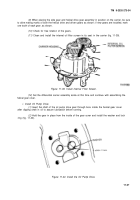
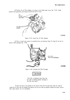
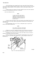
Check the bearing end play using a dial indicator mounted against the nose of the input
shaft (fig. 11-49). Use a dial indicator with a magnetic base or c clamp arrangement mounted on the
helical gear cover.
Figure
11-49.
Check Input Bearing End Play.
11-44
Back to Top

