TM-9-2330-342-23-P - Page 797 of 1348
INSTALLATION - Continued
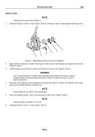
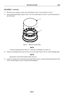
LIFTING DEVICE
1
NIPPLE
2
4
3
SOCKET
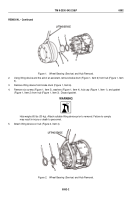
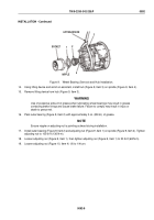
Figure 9.
Wheel Bearing (Service) and Hub Installation.
14.
Using lifting device and aid of an assistant, install hub (Figure 9, Item 3) on spindle (Figure 9, Item 4).
15.
Remove lifting device from hub (Figure 9, Item 3).
WARNING
Use of excessive amount of grease when lubricating wheel bearings may result in grease
contacting brake linings and cause brake failure. Failure to comply may result in injury or
death to personnel.
16.
Pack outer bearing (Figure 9, Item 2) with approximately 3 oz. (89 mL) of grease.
NOTE
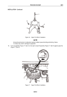
Ensure nipple on adjusting nut is pointing outward during installation.
17.
Install outer bearing (Figure 9, Item 2) and adjusting nut (Figure 9, Item 1) on spindle (Figure 9, Item 4). Tighten
adjusting nut to 100 lb-ft (136 N·m).
18.
Loosen adjusting nut (Figure 9, Item 1), then tighten adjusting nut (Figure 9, Item 1) to 50 lb-ft (68 N·m).
19.
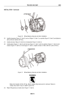
Loosen adjusting nut (Figure 10, Item 4) 1/6 to 1/4 turn.
TM 9-2330-342-23&P
0092
0092-9
Back to Top

