TM-9-2330-342-23-P - Page 987 of 1348
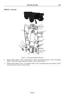
INSTALLATION - Continued
4
6
7
8
9
5
3
1
2
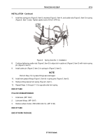
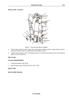
Figure 6.
Shock Absorber/Mount Installation.
4.
Position washer (Figure 6, Item 2), upper part of shock absorber (Figure 6, Item 3), washer (Figure 6, Item 4),
and locknut (Figure 6, Item 5) on upper shock mount (Figure 6, Item 1).
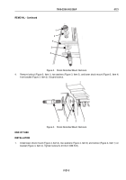
5.
Tighten locknuts (Figure 6, Item 7) and (Figure 6, Item 5) on mounting studs (Figure 6, Item 1) and (Figure 6,
Item 9) to 170 lb-ft (230 N·m).
END OF TASK
FOLLOW-ON MAINTENANCE
1.
Install slack adjusters. (WP
0078)
2.
Remove wheel chocks (TM 9-2330-342-10). (WP
0190)
END OF TASK
END OF WORK PACKAGE
TM 9-2330-342-23&P
0121
0121-5/6 blank
Back to Top

