TM-9-2330-342-23-P - Page 986 of 1348
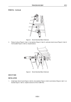
INSTALLATION - Continued
4
3
2
1
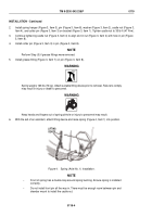
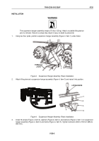
Figure 4.
Shock Absorber/Mount Installation.
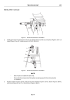
2.
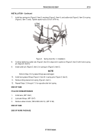
Install upper shock mount (Figure 5, Item 2), two washers (Figure 5, Item 3), and locknut (Figure 5, Item 1) on
frame (Figure 5, Item 4). Tighten locknut to 410 lb-ft (556 N·m).
1
3
3
4
2
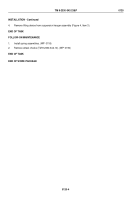
Figure 5.
Shock Absorber/Mount Installation.
NOTE
•
Both shocks are installed the same way.
•
Ensure that the concave side of the washers are facing away from the shock absorber
on installation.
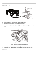
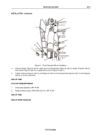
3.
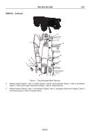
Position washer (Figure 6, Item 6), lower part of shock absorber (Figure 6, Item 3), washer (Figure 6, Item 8),
and locknut (Figure 6, Item 7) on shock mount (Figure 6, Item 9).
TM 9-2330-342-23&P
0121
0121-4
Back to Top

