TM-9-2350-238-20-1 - Page 1175 of 1364
TM 9-2350-238-20-1
NOTE
•
Install one track before removing
the other.
•
Procedures are written for one
track, but apply to both tracks.
1
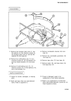
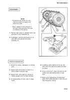
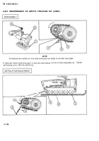
Lay track in straight line in front of vehicle
with track shoe grousers forward and track
touching first roadwheel.
2
Start engine and slowly drive onto track
until 11 track shoes extend past hub of
trailing idler wheel (1).
3
Stop engine. Leave parking brake off.
4
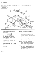
Insert driftpin in last track shoe pin hole.
5
Lift end of track over idler wheel (1).
6
Start engine and slowly move vehicle
forward. Guide track over roadwheels to
prevent end from getting caught between
roadwheels. When track reaches drive
hub sprocket (2), pry or lift it over sprocket.
7
Using drive hub sprocket, bring ends of
track together.
8
Remove driftpin.
9
Install two track connecting fixtures.
10
Apply corrosion preventive sealant to track
shoe link pin (3). Install track shoe link pin
and two new self-locking nuts (4). Tighten
self-locking nuts to 180 to 200 ft-lb (218 to
272 N-m).
2-202. MAINTENANCE OF SPEEDOMETER, TACHOMETER, AND RELATED PARTS.
This task covers:
a.
Removal
b.
lnspection/Repair
c.
Installation
INITIAL SETUP
References
TM 9-2350-238-24P-1
Equipment Conditions
2-935
Hull engine compartment deck assembly lid removed
2-938 Hull transmission compartment deck assembly removed
2-1149
Back to Top

