TM-9-2350-256-10 - Page 665 of 796
INSTALLATION
NOTE
If a track shoe was only removed to shorten track, start with Step 2. Release more track
tension as you are tightening track connecting fixtures.
1.
Place new track shoe assembly (Figure 6, Item 4) in position.
NOTE
If a track shoe was only removed to shorten track, install two end connectors and one
center guide.
2.
Tighten two track connecting fixtures (Figure 6, Item 3) until four end connectors (Figure 6, Item 5) can be
installed on track shoe assembly pins (Figure 6, Item 8).
3.
Install four new end connectors (Figure 6, Item 5) until end connectors contact track connecting fixtures
(Figure 6, Item 3).
4.
Remove two track connecting fixtures (Figure 6, Item 3) from the track shoe assembly pins
(Figure 6, Item 8).
5.
Hammer end connectors (Figure 6, Item 5) into position. Install four new wedge bolts (Figure 6, Item 7) and
new metal wedges (Figure 6, Item 6). Tighten four wedge bolts.
6.
Install two new center guides (Figure 6, Item 11) and new caps (Figure 6, Item 10) on track shoe assembly
(Figure 6, Item 4) with new screws (Figure 6, Item 9) and new self-locking nuts (Figure 6, Item 1). Tighten
self-locking nuts. Mark track shoe assembly.
7.
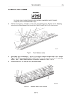
Unchock vehicle (WP 0103). Move vehicle (WP 0014) so that track shoe assembly (Figure 6, Item 4) is
positioned just over idler wheel (Figure 6, Item 2). Angle between track shoes should be approximately
16 degrees.
Figure 6.
Track Shoe Assembly Installation and Positioning.
TM 9-2350-256-10
0112
0112-7
Back to Top

