TM-9-2350-260-20-1-2 - Page 673 of 772
TM 9-2350-260-20-1-2
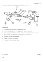
ACCELERATOR CONNECTING LINK ASSEMBLY REPLACEMENT (Sheet 3 of 4)
INSTALLATION:
1.
Screw jamnuts (A) and (B) all the way on ends of connecting link (C).
2.
Screw clevises (D) and (E) on ends of connecting link (C) the recorded number of turns.
3.
Using wrench, tighten jamnuts (A) and (B) securely against devises (D) and (E) while holding devises with pliers.
4.
Position connecting link assembly in tank and install pin (F) in clevis (E) and lever (G).
5.
Using pliers, install new cotter pin (H) in pin (F).
6.
Install pin (J) in clevis (D) and in rod end (K).
7.
Using pliers, install new cotter pin (L) in pin (J).
Go on to Sheet 4
TA148511
7-404
Back to Top


