TM-9-2350-260-20-1-2 - Page 81 of 772
TM 9-2350-260-20-1-2
REAR POWERPLANT GUIDE (LEFT AND RIGHT) REPLACEMENT (Sheet 1 of 2)
TOOLS:
9/16 in. socket with 1/2 in. drive
Hinged handle with 1/2 in. drive (breaker bar)
Ball peen hammer
Long round nose pliers
Slip joint pliers
Chisel
Brass drift
SUPPLIES:
Cotter pin (MS24665-136)
Connecting ring (8744683)
Sleeve bearing (5160090)
Wood block, 4 in. x 6 in. (approximately)
Lockwasher (MS35338-46)
PRELIMINARY PROCEDURE:
Remove powerplant (page 5-1)
REMOVAL:
1.
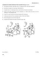
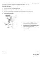
Using socket remove screw (A), lockwasher (B), and flat washer (C) securing rear powerplant guide (D) to support.
Throw lockwasher away.
2.
Using hammer, tap guide (D) from mounting place.
Remove guide from tank.
3.
Using punch, drive bearing (E) from support.
Throw bearing away.
4.
Using long nose pliers, remove cotter pin (F) and
latch (G).
Throw cotter pin away.
5.
Using chisel, cut ring (H).
6.
Using slip joint pliers, separate ring (H) and
remove ring (H), spring (J), and pin (K).
Throw
ring away.
Go on to Sheet 2
TA147459
6-4
Back to Top


