TM-9-2350-260-20-1-2 - Page 89 of 772
TM 9-2350-260-20-1-2
TRANSMISSION MOUNTS (LEFT AND RIGHT) REPLACEMENT (Sheet 4 of 4)
3.
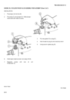
Using pliers, install lockwire (Item 59, Appendix D)
(D) between bushing (C) and bracket (A).
4.
Remove from vise and position bracket (A) onto
transmission and, using 3/4 inch socket, install
three screws (E) and new lockwashers (F) through
mount on transmission into bracket (A).
Leave
screws loose.
5.
Position spacer (G) into bracket (A) and install bolt
(H) through spacer (G), mount (A), and washer (J).
6.
With second person using 1-1/2 inch wrench to
hold bolt (H), use 1-1/2 inch socket and torque
wrench to tighten nut (K) to 380-415 lb-ft (515-562
N
•
m).
7.
Position roller (L) onto screw (M) and install screw
(M) through bracket (A).
8.
Using bit screwdriver and 1/2 inch drive ratchet to
hold screw (M), use 1-5/16 inch wrench to install
new self-locking nut (N) into screw (M).
NOTE
It may be necessary to turn universal
to gain access to screw (E).
9.
Using torque wrench and 3/4 inch socket, tighten
screws (E) to 70-75 lb-ft (95-102 N
•
m).
10.
Install 2A powerplant (page 5-14) or 2D
powerplant (page 5-40).
End of Task
TA147466
6-12
Back to Top


