TM-9-2350-261-20-2 - Page 813 of 1008
TM 9-2350-261-20-2
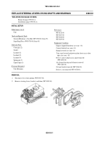
REPLACE STEERING LEVERS CROSS-SHAFT LINKS
0391 00
THIS WORK PACKAGE COVERS:
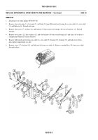
Removal (page 0391 00-1).
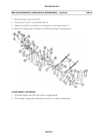
Clean, Inspect, and Replace (page 0391 00-2).
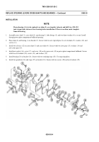
Installation (page 0391 00-2).
INITIAL SETUP:
Maintenance Level
Unit
Tools and Special Tools
General Mechanic’s Tool Kit (WP 0780 00, Item 29)
Materials/Parts
Cotter pin (4)
Personnel Required
Unit Mechanic
References
WP 0290 00
WP 0387 00
WP 0390 00
Equipment Condition
Engine stopped/shutdown (see your -10)
Carrier blocked (see your -10)
Trim vane lowered and power plant front access door
open (see your -10)
Driver’s power plant access panel removed
(WP 0430 00)
Brakes released, steering levers full forward (see your
-10)
Air cleaner housing and element removed (WP 0185 00)
Oil can bracket removed (WP 0524 00)
REMOVAL
1.
Disconnect two return springs (WP 0387 00).
2.
Remove cross-shaft cover from power plant compartment bulkhead (WP 0390 00).
3.
Remove four cotter pins (1), clevis pins (2), and two links (3) from steering levers and differential cross-shafts. Discard
cotter pins.
039100-1
Back to Top


