TM-9-2350-261-20-2 - Page 822 of 1008
TM 9-2350-261-20-2
REPLACE DIFFERENTIAL CROSS-SHAFT LINKS — Continued
0393 00
CLEAN, INSPECT, AND REPAIR
1.
Check link rods. Replace cracked, bent, or broken links.
2.
Check link clevises. Replace links with cracked or worn mounting holes.
3.
Check clevis pins. Replace worn or grooved clevis pins.
4.
Check springs. Replace cracked or worn springs.
INSTALLATION
1.
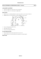
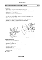
Install two links (3) to differential steering levers (4) and differential cross-shafts (5). Secure with four clevis pins (2)
and new cotter pins (1).
2.
Adjust linkage (WP 0387 00).
3.
Connect two return springs (WP 0387 00).
FOLLOW-THROUGH STEPS
1.
Close power plant front access door and raise trim vane (see your -10).
2.
Operate steering levers to check that differential cross-shaft links operate properly.
END OF TASK
0393 00-2
Back to Top


