TM-9-2350-261-20-2 - Page 852 of 1008
TM 9-2350-261-20-2
ADJUST ACCELERATOR AND TRANSMISSION THROTTLE VALVE
LINKAGE — Continued
0401 00
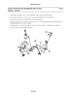
ADJUST UPPER ACCELERATOR PEDAL TOE STOP
1.
Remove screw (1), nut (2), and throttle link (3) from outer transfer shaft (4).
2.
Depress upper accelerator pedal (5) until transmission arm (6) is in full open position.
3.
Adjusttoestopscrew(7)infloorbracket(8)to1/16inch(2mm)spacebetween upper accelerator pedal (5) and screw.
4.
Install throttle link (3) on outer transfer shaft (4). Secure with screw (1) and nut (2).
5.
Adjust detent plunger if necessary. See ADJUST UPPER ACCELERATOR DETENT PLUNGER Steps 1 - 2.
6.
Check operation of accelerator controls and transmission shift points. See CHECK OPERATION Steps 1 - 10.
0401 00-8
Back to Top


